Process chain for the manufacture of thermally coated cylinder bores
by Dipl.-Ing. (FH) Gerhard Flores, Gehring Technologies GmbH, Ostfildern. Author profile: www.thermal-spray-bulletin.info/?id=205918, gerhard.flores@gehring.de
Summary
Thermally sprayed cylinder bores are manufactured in a complex process chain. The roughening using a variant of fine drilling is followed by the HVOF process as a thermal wire spraying process. The subsequent water blasting serves to eliminate the overspray underneath the bore in the crankcase. The concluding honing produces a liner surface which has superior tribological properties and is appropriate for the functions. Due to the diverse interactions between the individual process steps and the work result, complex understanding of the process chain and its parameters is required for the implementation by means of fabrication technology.
1. Introduction
The motivation for the utilisation of thermally sprayed coats in internal combustion engines originates from the advantageous functional properties of cylinder tracks manufactured in such a way [1]. Low friction as well as high wear resistance, thermal conductivity and ductility are essential prerequisites for the tribological suitability. Furthermore, a defined porosity and a high adhesive strength ensure component properties for safe operation. As a result of thin remaining coat thicknesses, it is possible to reduce overall engine lengths and to save weight in comparison with the cast iron liners used until now.
A process chain which produces high-quality workpieces with high process certainty and in the cycle times customary in engine fabrication is needed in order to achieve such engine properties. It can be put into effect with high productivity due to the technologies utilised on the basis of the far-advanced development status and to the high degree of automation.
In this respect, the final-machined cylinder liner surface has the functions of guaranteeing a suitable friction pair in interaction with the piston rings, of guiding these and, at the same time, of sealing the combustion chamber from the crank space in order to thus prevent an increased blow-by. Not only a microtopography appropriate for the requirements but also stringent macrogeometrical requirements are necessary for this purpose. The fabrication steps needed to this end consist of the mechanical roughening, the thermal wire spraying, the overspray blasting and the multistage honing.
2. Pretreatment by means of roughening
A suitable roughening process is required in order to permit a strong joint between the coat and the substrate. Roughness profiles which allow an adhesive pull strength of min. 25 MPa are manufactured in this respect. A large number of variants of mechanical roughening which work in an exclusively chip-producing method or also with additional profile forming were developed. One common feature of nearly all the roughening processes is a roughness profile which has undercuts and enables the desired adhesive pull strength due to adhesion, lateral shrinkage stresses and radially directed positive locking. The roughening profile on Fig. 1 was created without any profile forming and exhibits a profile depth of approx. 100 μm and a profile period length of approx. 300 μm. The attainable adhesive pull strength increases along with the profile depth. An adhesive pull strength of 45 MPa is exceeded with a profile depth of approx. 100 - 120 μm [2].
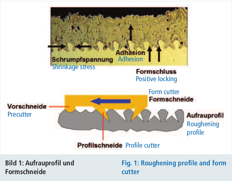
The undercut-roughening profile shown on Fig. 1 is produced by a polycrystalline diamond cutter which exhibits a complex geometry. A precutter serves to decrease the removal during the roughening by the downstream profile cutters in order to reduce the loads on the following cutters with a very filigree shape. The profile cutters are arranged according to the advance so that the first profile cutter initially cuts a sawtooth-like contour on which the second profile cutter arranged thereafter in the opposite direction is then superimposed. The dovetail profile created in this way exhibits distinct undercuts which exert an advantageous influence on the adhesive pull strength due to positive locking.
3. Thermal coating
The series fabrication of coated cylinder bores concentrates on the application of wire coating processes. With regard to the production costs and the fabrication certainty, these are superior to the powder coating processes. Thin sprayed coats with a thickness of 0.2 - 0.6 mm are applied. This results in a quasi-monolithic cylinder block with good thermal properties and, because of the low remaining coat thicknesses, in engines with shortened overall lengths and significant weight savings. The heat is dissipated very quickly due to the close bond between the coat and the substrate. Thus, the engine temperature is substantially lower than in the case of engines with a conventional design. Depending on the process parameters, the rapid cooling of the sprayed material leads to amorphous coats which have hard material dispersions (e.g iron oxides) if necessary and give rise to a high hardness and wear resistance of the coat. The hardness of the coat can be determined by the C content of the spraying consumable (such as unalloyed Fe wire).
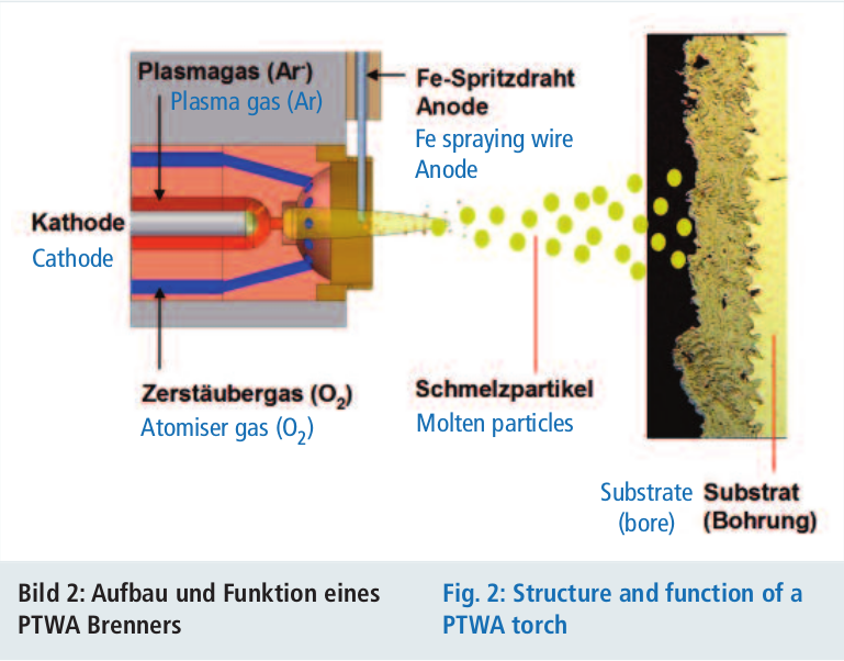
The coating process on Fig. 2, executed as the PTWA process [3], guides the spraying material in the form of the iron wire into the centre of the bore in a rotating torch. In a plasma arc between the tungsten cathode and the anodically poled iron wire, the iron material melts and is accelerated against the bore wall by the atomiser gas.
The coating process is determined by numerous parameters relating to the individual components of the process. Thus, the wire parameters are determined by the material, the wire diameter or the wire feed. For example, the spraying parameters are defined by the input energy and the flow of the atomiser gas. The size, temperature and velocity of the sprayed particles are determined in this way. The condition of the arising coating is determined by the characteristics of the coat material and of the surface parameters.
The coating result with regard to the coat material is of functional significance and is determined by the analysis, the density, the build-up structure, the porosity, the hardness and the ducility. The created coat topography consists not only of the spraying roughness but also of the structure and the overspray outside the bore.
4. Overspray blasting
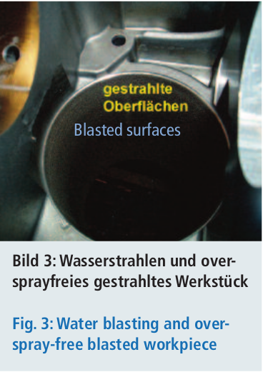
The overspray blasting has the task of removing overspray particles outside the bores, as a rule on the crankshaft side. This serves to avoid the detachment of sprayed particles in the operation of the engine which could cause increased wear in the overall tribological system of the engine. For the overspray blasting, a blasting lance is guided through the bore into the case. The blasting lance is designed with several inclined nozzles so that the water jet is incident between the overspray and the substrate in a wedge shape and thus detaches the overspray particles. Depending on the roughness of the cast surfaces, a pressure of 300 bar is sufficient [4]. Because of this water blasting technique, there is no need for any masking before the coating process (Fig. 3). This has made it possible to substantially increase the automation capacity of the process chain.
5. Honing
In order to manufacture a functional liner surface in the cylinder from the surface rough from spraying, honing must be carried out in several stages. In contrast with the machining of conventional materials such as grey cast iron or aluminium, the surface rough from spraying, the hard material inclusions, the pores and the adhesive pull strength have effects on the honing process. In particular, the rough surface after the coating and the oxide inclusions exert an extremely abrasive effect on the metallic bond of the honing strips on the coat side. This bonding wear leads to a reduction in the service life since the diamond crystals are thus detached from the matrix prematurely. Economically viable service lives are possible using hard bonding materials, high diamond concentrations with a splinterable grain structure and a force/displacement-controlled engagement device. On the other hand, the hard materials result in the preservation of the cutting capacity of the honing strips. For this reason, thermally sprayed coats (especially those with hard material dispersions) are easy to machine.
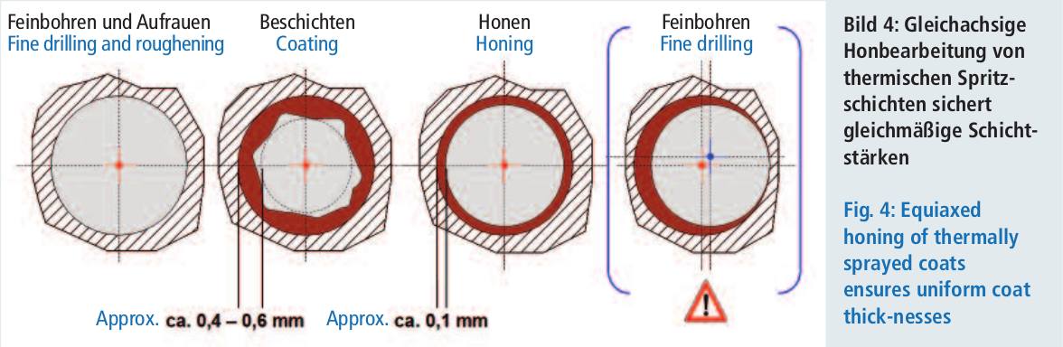
One essential characteristic of the honing of thermally sprayed coats is the equiaxed arrangement of the bore axis and the tool axis. The thermal coating also takes place in the bore axis previously created during the fine drilling and the roughening. The coat thicknesses are approx. 0.3 - 0.6 mm. Honing with a hinged tool holder is necessary in order to obtain a bore with a homogeneous coat thickness. Thus, the tool can be centred in the coated bore during the radial engagement of the honing strips and, from this position, can carry out chip-producing machining down to a uniform coat thickness (Fig. 4). As a rule, the remaining coat thicknesses are approx. 0.1 mm. The fine drilling or also honing of coated bores on machining centres is critical. Here, the axial position of the tool and thus the axial position of the final bore during the process were not oriented to the position of the coated bore surface but instead to the tool axis stipulated by the machine system. Since this rigid tool axis is not identical with the axis of the coated bore, this constitutes unequiaxed machining which leads to axial misalignment and to non-uniform coat thicknesses at the circumference.
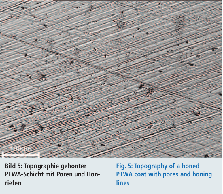
With regard to the machining result, particular surface dimension figures are of significance for the measurement of the final topography. Since the roughness profile consists of the superimposition of the honed roughness on the pores intrinsic in the material, special significance is attached to the surface dimension Rpk since, to a great extent, only the honed surface proportions are taken into consideration but not the pore size and depth. The differentiated determination of the oil retention volumes has proven to be suitable for the differentiated evaluation of the pore depth and the honed roughness depth. In this way, the oil retention volume of the honed roughness profile can be established separately from the oil retention volume of the pores. It is thus possible to separate the process technology influences of the honing process and the coating process.
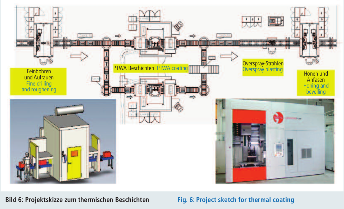
6. Implementation
The process steps discussed until now are arranged in a process chain as shown on Fig. 6. The crankcase is predrilled in the cylinder bore. The machining in the portrayed process chain begins with the fine drilling and the roughening on the PT module machine. This is followed by the double-cycle PTWA coating, the overspray blasting set up above the transport belt as well as the honing and the bevelling with a combined tool. An R4 block is available for the machining. The cycle time of the interlinked installation is planned at 90 s.
7 Summary
The described process chain includes a large number of new steps which benefit the quality, the machining time and the cost consideration. For the first time, the roughening method is designed as a chip-producing process. As a result of this, custom-built machines with high investment and operating costs are superfluous. The wire coating method ensures the cost-favourable manufacture of track coatings in a reliable process. Due to the overspray blasting, masking is no longer necessary during the wire coating process. This permits the further automation of the coating method. The concluding honing leads from the surface rough from spraying to the tribologically suitable piston track. This process chain corresponds to the trend in automobile construction, i.e. producing low-emission engines with reduced fuel consumptions and extended durability using new materials and cost-favourable fabrication technologies.
Expression of thanks
The process technology portrayed here is attributed to the research results which were elaborated in the project entitled "Nanocrystalline composite coatings for cylinder tracks with a nanostructured surface and wear prediction for petrol and diesel engines subjected to high loads - NaCoLab" promoted by the German Federal Ministry of Education and Research (promotion code: 03X0003). Particular thanks go to the Jülich Research Centre in the function of the project organiser, represented by Dipl.-Ing. Madeleine Dietrich who competently accompanied the joint project. 13 partners as representatives of all the relevant technologies were involved in the project with the total costs of € 11.5 million: Gehring GmbH & Co. KG, Ostfildern (overall responsibility), DURUM Verschleiß-Schutz GmbH, Willich-Schiefbahn, GTV mbH, Luckenbach, Opel Powertrain GmbH, Rüsselsheim, Porsche Engineering Group GmbH, Weissach, DaimlerChrysler AG, Ulm, Ford Werke GmbH, Cologne, Ford FZ Aachen GmbH, Federal-Mogul Burscheid GmbH, RWTH Aachen (IOT), University of Duisburg (WTII), University of Kassel (IMK) and University of Brunswick (IWF).
References
[1] Nakada, N., Ishikawa, Y., Yajima, J.: Der neue Hochleistungs-V6-Benzinmotor mit Doppelturbolader von Nissan, 17. Aachener Kolloquium Fahrzeug- und Motorentechnik 2008.
[2] Hoffmeister, H.- W.; Schnell, C.: Mechanical Roughning of cylinder bores in lightmetal crankcases; Production Engineering-Research and Development, Springer Berlin/Heidelberg, 2008, Ausgabe Volume 2, Nummer 4, Seite 365-370.
[3] Schwenk, A., Verpoort, C., Bobzin, K., Ernst, F., Richard, K., Schläfer, T.: Nanokristalline Beschichtung von Zylinderlaufbahnen im Rahmen des „Nanomobil“ BMBF Programms, VDI-Berichte Nr. 1994, 2008.
[4] Flores, G.: Innovationspotenzial neuer Honverfahren, Fertigungstechnisches Kolloquium Stuttgart 2010, Stuttgarter Impulse, Fertigungstechnik für die Zukunft, FTK 2010, Tagungsband, Seite 555.