Graded Freeform Machining of Cylinder Bores using Form Honing
by Gerhard Konrad Flores, Gehring
CITATION: Flores, G., "Graded Freeform Machining of Cylinder Bores using Form Honing," SAE Technical Paper 2015-01-1725, 2015, doi:10.4271/2015-01-1725.
Abstract
The use of form honing contributes to energy efficiency of modern internal combustion engines, especially to the reduction of CO 2 . Until now the production of internal combustion engines has required cylindrical bores with high shape and surface quality. This machined macro form is not maintained for the function of the engine due to mechanical and thermal influences. During operation they cause complex distortion mechanisms which significantly deviate from the desired cylinder form.
Therefore Gehring developed a form honing process that does not produce the cylindrical bore form as its goal, but gives instead the expected cylindrical deformations having the quasi cylindrical bore geometries under specific operational conditions. Furthermore the current development of form honing considers the friction of the piston skirt of the cylinder operation temperature with specific clearance in the lower part of the bore. This is possible without impairment of the NVH behavior of the engine.
The freeform for compensation of cylinder distortions and the local clearance for reducing friction at the piston skirt, can be applied in a complex form or used separately. Correlating to the high degree of freedom of form honing, all the functional advantages of freeform of cylinders bores can be achieved.
The principle of form honing, the process components, the serial production capability, the increased quality concepts and the achieved machining and functional results are described below. Consequently, form honing is an innovative contributor to the sustainability of the internal combustion engine. This paper describes the production process, which is available for the serial production of internal combustion engines. The test results of the fired engines are not the knowledge of Gehring Technologies GmbH.
Non Cylindrical Bore Shapes
Distortions of cylinder bores occur depending on static assembly deformations, dynamic forces and mostly by thermal influences. To obtain a quasi cylindrical bore at relevant operation points. These distortions will be pre compensated by form honing of non cylindrical macro shapes.
Depending on the stiffness of the crank case and on the heat input local radial shape deviations of 10 μm to 40 μm can be generated. Due to the limited shape filling capacity of the piston rings only an incomplete geometrical approximation to the distortion of the cylinder bore is possible. By local different contact of piston rings the blow by and oil consumption increased. Also the non cylindrical shape contains overlaid bottleneck contours in the lower part of the bore which reduces the contact of the piston skirt.
Compensation of Cylinder Distortions
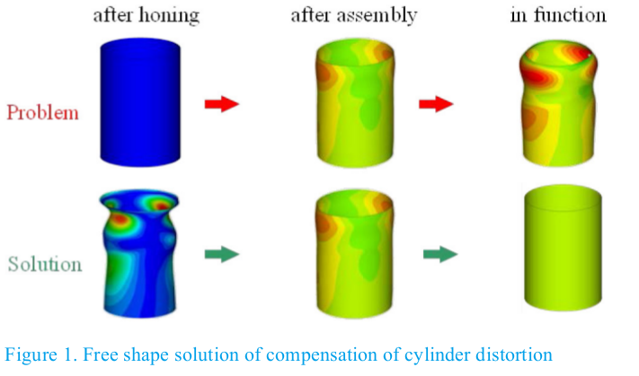
To fulfill the functional requirements of the cylinder bore, a honing process was developed to compensate of functional bore distortions. This means that the machining process allows to pre compensated the final functional deformations. Under defined fired conditions the non cylindrical bore will be deformed to an extensive cylindrical shape. This allows a reduction of piston ring tension and thus a fuel saving friction reduction. Figure 1 shows the principal solution for compensation of bore distortions.
Local Optimization of Piston Clearance
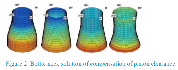
A further improvement of the tribological system piston/cylinder bore is based on the high part of friction of the piston skirt and third piston ring of 46 % compared with the part of friction of the first and second piston ring of 34 %. The remaining 20 % friction losses are generated in the conrod bearing [1]. The optimization of piston skirt clearance happens due to local different matching along the bore length. To minimize the piston secondary movement in the upper part of the bore a tight guidance of piston with less clearance is advantageous. The NVH-characteristic is positively affected. Within the lower part of the bore the piston is given a larger clearance to reduce the contact and by this to reduce the piston skirt friction [2]. Figure 2 shows different bottle neck shapes which are used for local optimization of piston skirt clearance.
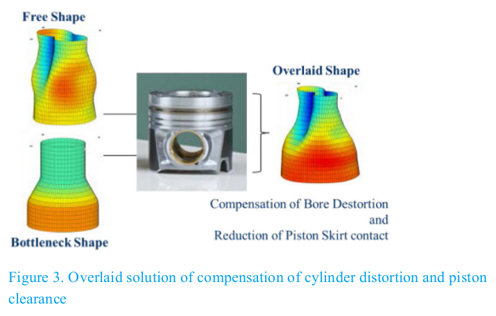
Both innovative solutions consist of the free shape for compensation of cylinder distortions and the local increase of piston skirt clearance for friction reduction. Both can be combined by an overlaid optimized shape (Figure 3) as well as by separate applications. Corresponding to the high degree of freedom of form honing the possible shapes from simple bottle neck or bell mouth shape to the complex free shapes with longitudinal and circumferential amplitudes are available in graded versions.
Principle of Form Honing
To define the free shape which is to be honed an experimental method is used. The engine block is deformed by a simulator torque plate and is hot honed cylindrically [3]. Further methods are the simulated calculation under consideration of cold static and thermal influences or also the use of pistons with applied gauging device for identification of cylinder distortions under fired conditions [4]. The evaluated distortion shape is to be inverted so that the specified lead shape as the non cylindrical target can be honed as the estimated precompensated shape.
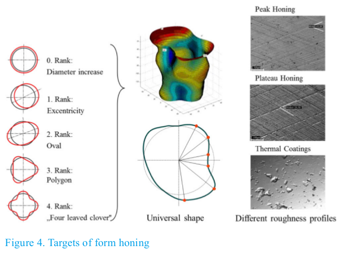
The target of form honing in Figure 4 consists of lead shape honing. This lead shape can be realized in free shapes with harmonic shape sequences up to 8 th rank. The shape is defined in several levels with circumferential appointed polar coordinates r/ρ. Beside the lead shape the requirement of a unique range of the roughness profile depth in all areas of the bore face exists. In all areas of the bores face, as it is in narrow or wide radial ranges and in the areas between the equal surface topology must be possible. This is to apply for conventional peak honing as well as for the complex topography definition of a plateau honing. Cast iron and thermal coatings are subjects of form
honing operations.
Components of Form Honing Process
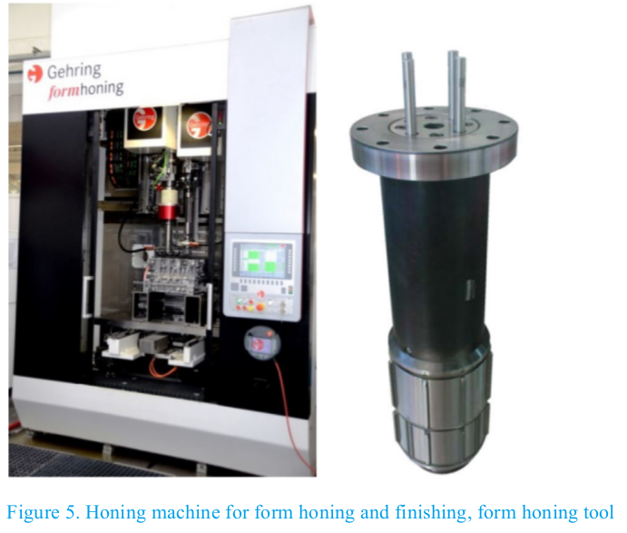
To realize form honing in serial production it is necessary to use the different innovations like dynamic feed systems, shape control, form hone tooling and finish tooling, diamond abrasives, device for automatic tool changes and a free shape qualified form gauging equipment. All these components can be used on a standard Gehring honing machine as shown in Figure 5 which have to be configured to this specific machining task.
The independent feeding of the single diamond honing shoes requires highest dynamic and accuracy of the used piezoelectric actuators.
For this purpose a multi actoric feed and tool concept was developed which contains of four independently expandable honing shoes [5]. In relation to the present axial and circular position of one single honing shoe radial feeding, feed force and feed way can be controlled in according to the r/ρ coordinates of the lead shape. In this mode the working surfaces of the honing shoes are moving on the path line which is conform to the defined lead shape.
The four honing shoes have only a close short stone length due to the short waved axial form characteristic. Therefore it is necessary that a constant local contact time of the working surface of the honing shoe is achieved at all over the bore face. This requires an adequate adjustment of the kinematic process parameters. In order to obtain the range of usual machining times of cylinder bores of passenger car engines of ≤ 30 s, cutting speeds are necessary which lead to the desired self-sharpening effect of metal bounded diamond abrasives. A rotational speed up to 400 1/min feed frequencies of up to 32 Hz allows form characteristics of 5 th order with radial amplitudes up to 60 μm. The mono actoric as well as the multi actoric piezo feed system are designed for simultaneous machining of two bores of one crank case in one station of a transfer or modular honing machine.
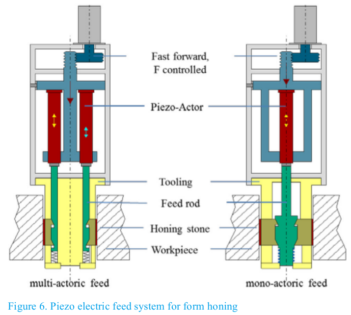
Figure 6 shows piezoelectric feed systems with fast forward, piezo actuators and form honing tools. The fast forward moves force controlled the set of piezo actuators and the honing shoes against the bore surfaces. From this radial position of the honing shoes the piezo actuators start working. In according to the lead shape the local different feeding is active. This means, depending on the single axial and circular position the honing shoe is expanded with local different feed ways with highest dynamic and accuracy.
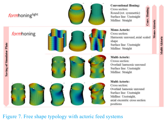
Figure 7 shows the typology of different free shapes. It contains bore shapes which are reliable obtainable with actoric feed systems. The multi actoric feed system allows the honing of all function relevant free shapes. This can be cross section profiles of harmonic unround shapes of different ranks. The axial surface lines are not straight, also curved or s-shaped centerlines can be generated. The simplified mono actoric feed system enables harmonic unround shapes only of one determined rank combined with curved and bottleneck shaped axial surface lines [5]. The rank of the unround shapes is depending on the number of honing shoes in the used tool. With conventional honing technology with honing shoes of different length and specific stroke adjustments and standard electro mechanical feed systems the machining times and the spread of accuracy deviation increase. Prototyping of single bottleneck or bell mouth shapes are possible, however not in the usual process capability of high volume production. Due to process conditions an irregular wear of honing shoes will be generated which does not allow a constant machining result. This mode requires a frequent regrinding of abrasives and leads to a reduced tool life and process economics.
In case of rotational symmetric uncylindrical shapes unround bore distortions are unconsidered so that a further use of simulator plates to pre compensated cold static deformations are still necessary.
After form honing of the non cylindric bore shape in a further operation for the final roughness profile as a peak or plateau profile have to be done. For this operation multi stone honing tools are developed with honing shoes which are segmented in single short sections in axial direction. Every single honing shoe segment is spring loaded so that the single segment can follow the previous form honed shape [5]. The used spring characteristic allows an almost constant stone pressure within the shape amplitudes. The length of the segment is like in the form honing tool also shorter than the wave length of the axial shape course of the bore. The form hone tool as well as the finish hone tool has a HSK interface for application of an automatic tool changer. The costs of abrasives per bore are nearly equal to conventional diamond honing processes.
The further process sequence after fine boring of the cylindrical shape is rough honing or position honing. The following process is carried out in one or two form honing operations (depending on the depth of shape amplitude) and followed by the finish operation. To achieve high process stability a post process form and diametral size gaging are necessary. A multi jet air gage mandrel with gaging range of 150 μm radial runs within 20 s and with a repeatability of ≤ 2 μm. This measurement device works robust and is insensible against vibrations, dust and dirt and can be applied on a post gaging station of the form honing machine. With this gaging equipment the shape can be measured as well as the diametral size which is used for the matching of the piston. A feedback control to the pre hone and form hone operation enables assured quality in serial production.
Results
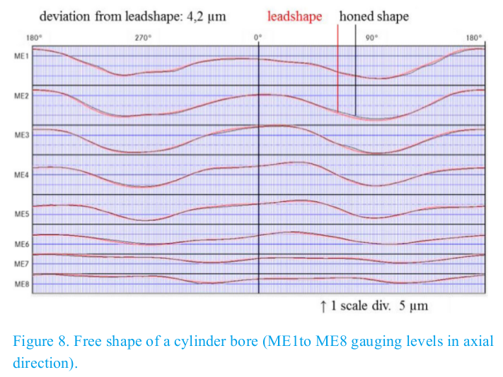
The current state of form hone technology delivers repeatable free shapes which deviate maximum ± 3 μm from the lead shape as figure 8 shows as a cylinder development. The total stock removal of form honing based on the cylindrical pre honed bore amounts depending on the shape amplitude min. 0,030 mm unto 0,050 mm on diameter additional to the radial shape depth.
The form toleration happens with the invention of envelope curves in distance of the defined tolerance width around the lead shape. Furthermore also the amplitudes of the single ranks are to be tolerated. This is an important quality feature because the waviness of higher ranks has an impact to the function of engine.
By subtraction of the lead shape from the real achieved shape an evaluation of the quality is possible. The cycle time of form honing process sequence is 50 s for a truck engine and 30 s for a passenger car engine. The piezo electric feed system is approved as a reliable, adequate exact and dynamic working technology.
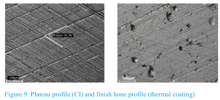
Beside the uncylindrical shapes also topographics with plateau and peak structures all over the bore surface can be achieved reliably. Figure 9 shows such a plateau profile of a cast iron surface and a finish hone profile with smooth honing pattern and material pores. In both materials the surface tolerances can be reached in the tops and valleys of the shape. The spread and variation of roughness is comparable with the current cylindrical conventional honing process.
Summary/Conclusions
With the developed state of form honing technology by actoric feed systems any free shapes as well as bottleneck and bell mouth shapes are possible to be machined with shape amplitudes of more than 30 μm. However the most effective shape is the overlaid shape of bottleneck and free shape. Form honing has a high technological readiness level. Surface quality, cycle times and costs of abrasive per bore are comparable with the conventional honing process. Significant functional benefits at the fired engine concerning oil consumption and CO 2 - emissions are approved. Form honing demands a complete adjustment of the complete tribological system. Therefore the piston and piston ring package must be adapted to uncylindrical shape concerning ring tension and geometric design.
Form honing allows the substitution of simulator plate and provides not only functional benefit but also benefits of production with cost reduction. Furthermore extensive experiences are available with passenger car engines, truck engines and stationary heavy diesel engines. Cast iron as well as thermal coatings can be form honed. The introduction in serial production is in preparation with current customer projects. The first multi spindle customized form honing machine in the meantime has been delivered.
This form honing technology is an innovative sustainable manufacturing process which provides an improvement of efficiency, also a significant reduction of CO 2 - emissions of modern internal combustion engines is possible. Based on the available knowledge and experience the preconditions for serial application of engine blocks and single cylinder liners are given.
References
1. Schommers, J.; Eder, T.; Behr, T.; Lagemann, V.; Weller, R.; Böhm, J.; Schnüpke, H.; Binder, S.; Dietz, W.: Steel Piston for Diesel Passenger Cars Engines - Efficient, Sustainable and Light, Daimler AG, Stuttgart, 23rd Aachen Colloquium Automobile and Engine Technology 2014
2. Property right DE 10 2011 117 660 A1 (08.05.2013), Audi AG, Pr.: DE 10 2011 117 660 04.11.2011. - Brennkraftmaschine
3. Wiens, A.; Lahres, M.; Hoffmeister, H.-W.; Flores, G.: Fertigungstechnischer Ansatz zur Kompensation von Zylinderverzügen mittels Formhonen. VDI-Berichte Nr. 2109, (2010), VDI-Wissensforum GmbH, Düsseldorf, Seite 133 - 145,
4. Möndel, A.; Jablonski, J.; Ingelfinger, U.; Rosenbeck, M.; Theisen, P.; Orlowski, K.; Plettenberg, M.: Analysen zur Kolbenbewegung eines Hochdrehzahlenmotors unter Berücksichtigung der Anregungsquellen im Kurbeltrieb. VDI-Berichte Nr. 2109, (2010), VDI-Wissensforum GmbH, Düsseldorf, Seite 259 - 272
5. Wiens, A.: Formhonen von Zylinderlaufbahnen. TU Braunschweig, Institut für Werkzeugmaschinen und Fertigungstechnik, Dissertation, 2011
Contact Information
gerhard.flores@gehring.de
andreas.wiens@gehring.de
Acknowledgments
Beside the co-author also Andreas Wagner (process development) and Klaus Litty (software and control) gave a great contribution to development of the form honing process. Thanks for their creative and competent support.
The Engineering Meetings Board has approved this paper for publication. It has successfully completed SAE’s peer review process under the supervision of the session organizer. The process requires a minimum of three (3) reviews by industry experts. All rights reserved. No part of this publication may be reproduced, stored in a retrieval system, or transmitted, in any form or by any means, electronic, mechanical, photocopying, recording, or otherwise, without the prior written permission of SAE International. Positions and opinions advanced in this paper are those of the author(s) and not necessarily those of SAE International. The author is solely responsible for the content of the paper. ISSN 0148-7191 http://papers.sae.org/2015-01-1725