Machining and Characterization of Functional Surfaces of Thermal-Coated Cylinder Bores
by Gerhard Flores , Andreas Wiens , and Manuel Waiblinger
Abstract
Machining of thermal-sprayed layers is a new challenge for machining cylinder bores with different honing variants. New strategies for machine and tool layouts as well as in particular the availability of appropriate diamond stones considering the material-specifi c properties of the cutting process are essential. Based on the coating material characteristics which are relevant for machining, a new honing process is presented.
Following the material properties of thermal-sprayed layers, the machining task, the process layout and the obtained quality values are described. Also the different variants of machining strategies are indicated, which are applicable for the different
thermal-sprayed layers. The paper describes the machining results regarding the functional properties.
Keywords:
Thermal coating • Wire coating method • Powder coating method • Roughening method • Bond strength • Rough honing • Position honing • Material stock removal • Process chain • Layer thickness • Diamond honing shoes • Finish honing • Topographic features
1 Introduction
The machining and characterization of thermal coatings with different spray technologies based on a rough surface as sprayed has the target to obtain a functional surface topography of a quasi-monolithic cylinder block. The different layer qualities offer favourable conditions for further friction and wear reduction in modern combustion engines. The machining task is described regarding relevant material properties of thermal coatings. Different honing processes are presented which lead to cylinder bore surface topographies with low friction. The paper concludes with the discussion of the machining results, the reference to experience in serial production and an outlook at further process developments.
2 Material Properties of Thermal-Sprayed Layers
The following indicated material properties are selected concerning their importance for the mechanical machining. Layer parameters like porosity, ductility or residual stress condition are less relevant for machining.
The thermal-sprayed layers used for cylinder bores of combustion engines are realized by wire or powder coating methods. As wire coating method, the LDS (wire arc spraying) and the PTWA method (Plasma Transferred Wire Arc) are applied. Also used in serial production is the APS powder coating method (atmospheric plasma spraying). The layer structure is differently scaled depending on the coating method and on the used parameters. In any case, the layer consists in single spray particles (droplets) which hit the substratum surface in liquid or pasty condition and which are piled up as a layer with lamellar structure. Generally the substratum is the pretreated aluminium surface of the cylinder bore. This surface shows a microtopography with as many as possible undercuts, so that in case of suitable roughening profi le depths, there is a strong and tight bond between the sprayed layer and the substratum by microform fi t, shrinking strains and adhesion. This is possible, e.g. by corundum blasting, high pressure water jetting or different variants of mechanical roughening of aluminium substrate. There is also the possibility to use a NiAl adhesive layer between a cast iron substratum and the layer. These processes are approved in serial production and assure suffi cient bond strength [ 1 ].
Due to their high kinetic energy, the spray particles are placed fl at deformed on the surface evenly. Depending on the specifi c coating method, the lamellar layer structure of approx. 0.200–0.600 mm coating thickness (radial) grows up successive by hitting the spray particles on the substrate surface. For the mechanical machining of thermal-sprayed layers, not only the adhesive quality with regard to the substratum is of great importance but also the strongest possible cohesive strength of the particular sprayed particle. This material structure is the result of local melting or mechanical micro-clamping.
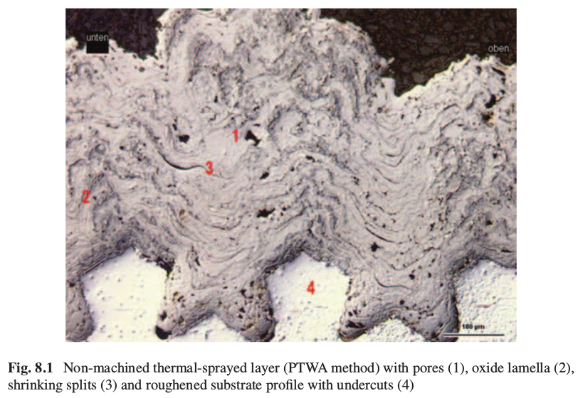
Figure 8.1 shows the example of a thermal-sprayed layer structure. The layer has pores (1), grey oxide lamella near the profi le edges of the roughening structure (2) and shrinking splits between the sprayed particles piled up on each other (3) which are caused by the residual stress during the cooling process. The roughening profile with the dovetailed undercuts is also visible (4).
The oxides of a layer have great infl uence on the tool lifetimes as the oxides cause an abrasive wear effect on the honing stone surface. In addition to the layer structure with oxides and pores, also the surface profi le as sprayed with a roughness between approx. 20 and 200 μm R z has a disadvantageous impact on the tool lifetime for mechanical machining of the layer.
As materials, iron wires with 0.3 % or 0.8 % C are approved in serial production in the meantime. These ferrous layers can be also generated under use of protective gas with a low oxide content of few vol.-% (volume percent) produced only. Without protecting gas, produced Fe coatings enclosed oxides of 15–20 vol.-%. Oxides in the Fe layer exist as wustite FeO, haematite Fe 2 O 3 or magnesite Fe 3 O 4 . The micro- hardness of the layer is approx. 300–600 HV 0.3 depending on the carbon content. It appears that there are further demands on increased corrosion resistance. Layers with very high chrome content made by pre-alloyed wires or fi lled tube wires are not yet generally accepted as their tribological properties are insuffi cient. For thermal powder coating methods, non-alloyable materials can be sprayed together. Therefore it is possible that also wear-resistant ceramic hard materials can be put into a corrosion-resistant matrix in order to fulfi l the tribological and the chemical requirements.
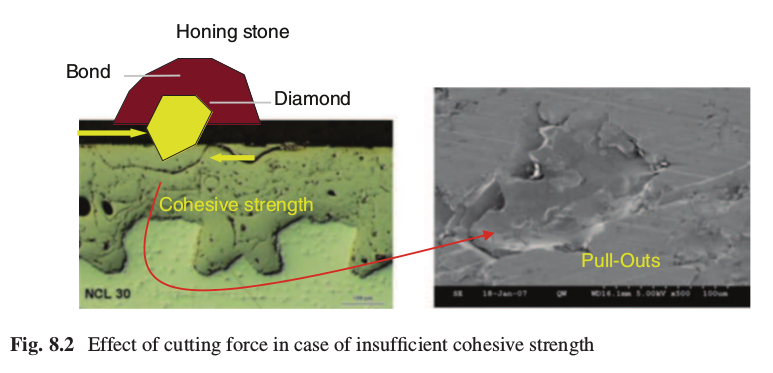
As the thermal-sprayed layer is an inhomogeneous material, there is the intention to create a strong binding among of the single droplets. In practice it cannot be avoided that even with defensive machining parameters single melting particles are put out and so-called pull-outs are caused. This happens when the cutting force of the diamond grit is bigger than the cohesive strength of the layer. Then a non-disturbed cut of the diamond grits of the honing stone through the proper material cannot be carried out (Fig. 8.2 ).
The coated layer and the roughening method are to be laid out accordingly that the adhesion between layer and substratum is bigger than the cohesion within the layer. Having such conditions, the layer can be well machined without any risk that the cutting forces will remove single droplets or extensive large-scaled layer sections.
If a layer withstands the conditions of the honing process, then there is a very low risk that the layer will be detached during operation as the machining forces are much higher than the shearing forces of the piston ring friction during the fired running of the engine. Bond strengths of at least 30 MPa are required as minimum condition. They are achieved by various procedures of the pretreatment.
3 Machining Task
As already mentioned, the thermal coating of cylinder bores is initially a process step by which a compound material as protective surface layer is put into the bore. The macroform of the substratum is not really an equidistant reproduction on the layer surface which is largely prevented by high roughness, pads on the bore edges or other material artefacts as local uneven layer thicknesses. The profi ling of a functional surface is not the fi rst goal and ability of a coating method but rather the ask of the following machining process.
Principally the machining task is to achieve a designed smooth and functional surface starting with the rough sprayed layer surface of a cylinder bore. For this reason numerous quality parameters are defi ned and tolerated according to their function. The fi nished condition of the cylinder bore has to meet the functional requirements with diameter, roughness as well as form and position tolerances. Furthermore machining times as short as possible are demanded which can be realized by robust cutting parameters with high stock removal rates only. All following indicated tolerances are approximate values which can be achieved reliably in serial production. However, in individual cases the engine-specifi c requirements are to be considered which can lead to other than the given tolerance ranges.
In order to get functionally coated cylinder bores, the macroform size and cylindricity is primarily described with suitable measured tolerance values. The accuracies of the direction and position of the bore are defi ned by the quality values’ rectangularity and position accuracy. As form tolerances the cylindricity and if applicable also roundness and straightness are used. Regarding dimensional accuracy, there is no difference between a coated bore and a conventional cylinder bore of cast iron or aluminium silicon compound material. The microform of a coated bore described the topographical surface parameters. They are not only given by fi nish honing process but also by inhomogeneities immanent to the layer-like pores and pull-outs. In Fig. 8.3 the relevant quality features for the function including their respective approximate tolerances are summarized. They are based on the experience with passenger car engines. For coated cylinder bore liners of utility and marine engines of bigger sizes, there are no generally applicable indications.
| Feature | Approximate Tolerance |
| Makro form | |
| Rectangularity | ca. 0,050 mm for bore length |
| Position | +/- 0,1 mm |
| Cylindricity | ≤ 10 μm |
| Diameter | ca. +/- 0,010 mm |
| Mikro form | |
| Reduced peak height R pk | ≤ 0,25 μm |
| Average roughness R z | ca. 5 μm |
| Cross hatch | ca. 30° |
| Layer parameter | |
| Porosity | 2 – 6 % of considered face (PTWA) |
The indication of the rectangularity is valid not only in the direction of the crank bore axis but also crosswise to it. Dependent on the function, it can be possible to specify a smaller tolerance range in axial direction and a wider one crosswise to it. The bore axis position is independent of the direction. Concerning the topographic parameter, only the reduced peak height R pk and the cross-hatch are determined by fi nish honing. The R pk value delivers the microcontact topography of the layer to the piston. This contact surface should be as smooth as possible so that the percentage contact area consists of the biggest possible number of contact points and reduces the slide friction hereby. However, for Diesel engines a R pk value can be advantageous to increase the oil retention volume also in the honed profi le elements by R pk values up to 0.30 μm. Furthermore the roughness of the bearing contact profi le is to be considerably smaller than the depth of the opened pores in order to support the function of the pores as micropressure chambers for the hydrodynamic lubrication. The mean roughness depth R z or also other measured values like core roughness depth R k or the reduced groove depth R vk are mostly dependent on the inhomogeneity of the layer structure.
Besides the quantitative evaluation of the macro- and microforms, there are further requirements with regard to the topographic structure quality. The still remained visible honing grooves are to be continuously cut. The smaller the honed roughness of the thermal-sprayed layer is, the smaller the oil retention volume of the honed topography. A fl at cross-hatch of 30° is favourable for the formation of the hydrodynamic lubrication. At the edges of the pores, as less as possible, material like burrs and folded material is to go into the cavities and close these consequently [ 2 ].
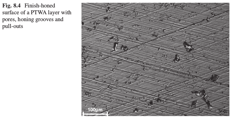
The pores and pull-outs are to be cut regularly on their edges and completely opened without any burrs. Finally a minimum of plastic deformation on the subsurface zone is to be achieved by low machining forces (Fig. 8.4 ). In addition it is required that beneath the surface, the layer structure is non-deformed as far as possible and the subsurface zone damage is minimized.
The material removal by honing in several steps can vary signifi cantly as per coating process and the specifi c layer parameters. The layer thickness of APS layers is approx. 0.200 mm [ 3 ] and of PTWA and LDS layers 0.300–0.600 mm [ 4 ]. The remaining layer thickness of the fi nished bore is 0.080–0.150 mm. The stock removal ranges for honing and the number of honing operations are different accordingly. The stock removal for honing is approx. 0.200–0.500 mm on diameter. The cycle time for machining of thermal-coated cylinder bores in passenger car cylinder blocks is approx. 30 s. For cylinder liners of big engines and for stationary engines or marine engines, the machining times can be even up to some minutes.
4 Process Layout
For the machining of thermal-coated bores, two process chains are developed essentially. One of the variants uses a rough honing process by removing the layer material in equidistant manner and without infl uencing the axial position of the bore. This results in a constant layer thickness along the complete bore. The rough honing is required in cases of low layer thickness and when a correction of the bore axis with minimal stock removal risks is to break through the layer locally. Therefore in case of thin APS layers, only rough honing can be done. The bore position accuracy has to show the end quality already before the coating process due to the thin layer thickness, so that the existing position and rectangularity qualities are maintained as far as possible.
Fine boring as an alternative to rough or position honing was tested, but it is not introduced in serial production up to now. Tool life is low due to the abrasive effect of the layer oxides. Lifetime of cutting edges is less than 1/10 of tool life of honing shoes in position or rough honing process. The local cutting forces of fi ne boring inserts are higher than the honing forces. This can lead to layer deformation, particle pull-outs, microfi ssures and extensive layer damages in the subsurface zone. In addition very smooth surfaces are produced which make the cutting for the following honing tool more diffi cult. However, honing tools with relatively large working surface of the honing stones cause low local forces to the surface only so that subsurface zone deformation is of minor extent [ 5 ].
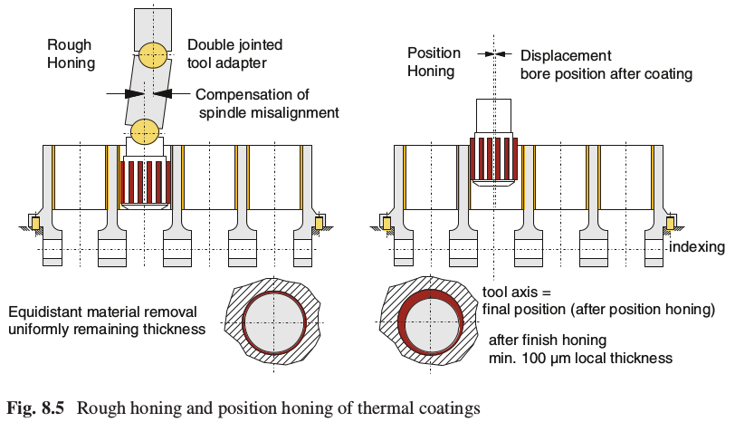
Figure 8.5 presents the different honing procedures for thermal-sprayed coatings. The rough honing tool follows the coated layer due to the fl exible tool adaption. There is no infl uence on the axis position of the bore. A constant layer thickness
is generated.
While rough honing as a cutting intensive process is quite often applied for coated cast iron liners, steel tubes and thin APS coated cylinder bores, position honing is a new process which is already used in serial production in some cases. Particularly for thermal-sprayed layers being hard, but due to their lamellar material structure having good cutting conditions, position honing is a process with high cutting volume. Due to the suitable material conditions, low subsurface deformations and good position accuracies are achievable [ 6 ]. The demand for a position and rectangularity correction of the bore results in a different machining concept. In comparison with the conventional process, position honing needs a fi xed axial tooling position which corresponds to the position and also the rectangularity of the fi nished axial bore position. When clamping the crank case, the position is defi ned by indexes which are related to the tooling axis [ 7 ].
During the position honing process, there is at the beginning a one-sided local cutting when the tool enters the bore. This restricted local stock removal is due to the position displacement between the bore and tooling axis. By increasing the stock removal during the cycle, machining covers fi nally the complete bore surface. When the machining of the total bore surface is achieved, then also position and rectangularity are given and now the tooling axis is identical with the bore axis. For this machining procedure high stock removals are necessary in order to get the best possible position correction. The remaining layer thickness of minimum 0.100 mm is to be respected. As an example, a layer thickness of 0.400 mm on a radius allows a theoretical correction of the position by 0.160 mm or of the eccentricity of 0.080 mm in case of a stock removal of 0.100–0.300 mm on a radius, with a remaining layer thickness of minimum 0.100 mm. This considers the local radial minimum stock removal of approx. 0.100 mm required to remove the spray roughness and allows a further radial stock removal of approx. 0.040 mm after position honing.
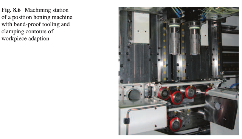
Figure 8.6 shows in particular the constructive features of a position honing machine. The tooling is attached to the spindle in a rigid way. To realize the required bending stiffness, the tooling is laid out as short as possible. As the requirements of the machining spindle for the position honing process are signifi cantly different from the conventional honing spindles, a spindle with increased stiffness and high revolution speed of more than 2,000 1/min is applied . Only by this condition the high stability along the complete drivetrain arrangement from the spindle to the tooling as well as the high stock removal rate and position accuracy are enabled. The crank cases are positioned at adjusted indexing points of the horizontal or vertical clamping device. There are also clamping contours on the workpiece. The two spindle layout of the machine is not due to the process technology, but it offers the possibility to shift the workpiece. Thus the simultaneous machining of two bores is given.
It can be mentioned that a pneumatic measuring system for size control is in serial application despite the high stock removal of up to 0.700 mm on diameter. The air nozzles are arranged as usual in the tooling. The cutting intensive process requires the coolant supply through the spindle.
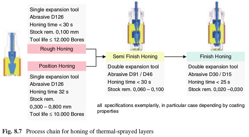
The process chain up to the fi nished cylinder bore starts as presented in Fig. 8.7 with rough honing or position honing. In case of layer thicknesses of 0.200–0.300 mm, rough honing is recommended. Alternatively there is the position honing process which is more important for higher layer thicknesses. The cutting intensive process is done with a stock removal of up to 0.600 mm. It can be indicated that tool lifetimes of up to 10,000 bores for position honing are possible depending on the layer properties. This is an important advantage compared to fi ne boring of thermal- sprayed coatings. The following machining of semi-fi nishing and fi nishing is done with two spindles. Semi-fi nish honing and also the following fi nish honing operation work with double feeding system. They each have two sets of carriers with honing shoes which are activated successively. Four different abrasive grit sizes are necessary to improve step by step the roughness of position honing or rough honing of minimum 20 μm R z up to fi nish roughness of approx. 5 μm R z and R pk value of 0.25 μm. Only diamond shoes with microsplitting crystals and metallicsintered bondings are in use. As usually hard material is embedded in the sprayed layer, the self-sharpening of the honing stones is given by the abrasive effect of the hard material particles. On the one side this effect assures the cutting quality of the abrasive stones, but on the other side, there are special arrangements to be taken to obtain economic tool life values.
The honing time is as mentioned before approx. 30 s. For the described process steps, the process chain requires at least three spindles, which have to be arranged for multiplication depending on the desired capacity.
The admissible process parameters like feeding pressure and cutting speeds highly depend on the cohesive and adhesive layer tensile strengths. In case of layer structures having low cohesive strength, low feeding pressures and speeds are
required. Otherwise the layer is pulled out locally and is detached in a lamellar manner. On the other hand there is experience with thick PTWA layers which can be machined with robust parameters due to high structure strength.
5 Machining Results
The size and geometry accuracies of thermal-sprayed bores correspond to the general values of cylinder bores and can be maintained reliably with the described process chain. By the taken measurements like increased stiffness of the drivetrain arrangement from spindle drive to position honing tool as well as the well-tolerated positioning of the workpiece by high-precision clamping contours, the position accuracies can be assured.
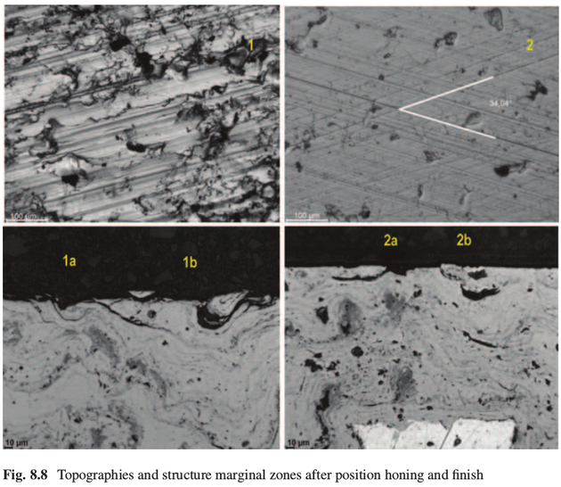
The indicated quality features in Fig. 8.3 are restricted signifi cantly also for the position accuracy by the statistic tolerances. Thus, under favourable conditions, rectangularity values within the bore length even under 0.030 mm are realizable. In the same way the mentioned position accuracy can be reduced considerably. The photos of the surfaces presented in Fig. 8.8 are taken after position honing, semi- fi nish honing and fi nish honing.
After position honing (1) a highly fi ssured surface structure is shown which is characterized dominantly by cutting fi ssures. Furthermore on the surface there are clear material displacements visible, which also cause oversmeared material at the pores. The surface after fi nish honing (2) represents the functional topographic structure. The views of the polished section surfaces show fi ssures (1a) and pullouts (1b) after position honing. A higher contact pressure of the honing stones is not allowed as it causes damage to the subsurface zone. After fi nish honing there is a smooth cut surface also with material out-pulls (2a) and pores in the subsurface zone just beneath the surface (2b) [ 8 ].
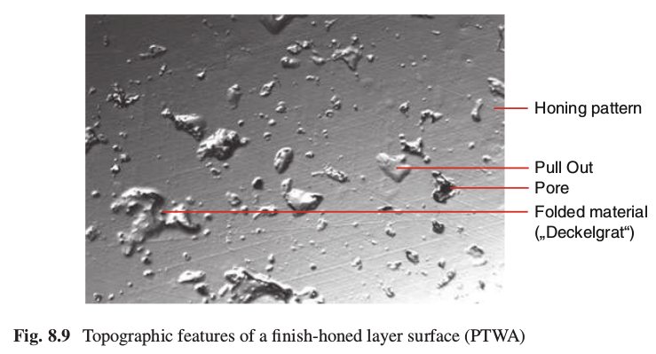
In Fig. 8.9 the particular topographic features of a fi nish-honed thermal-sprayed layer can be seen. The honing grooves are only slightly visible as the roughness is low. But they are evenly formed in both directions. The cut pores are visible as dark deepenings. They can be distinguished clearly from the pull-outs which show at the cavity bottom a bright and molten smooth surface. Therefore it is concluded that attached melting particles are removed by honing. Crushed melting particles are visible slightly as material doublings or as folded material.
Optical surface measuring methods are getting more and more important in order to characterize honed surfaces of thermal coatings. At the fi rst place, there is a three-dimensional detection of the topography compared to the tactile measuring systems often used up to now. In application white light interferometer and confocal measuring principles are used. This development supports the objectiveness of quality measuring [ 9 ]. Besides the 3D roughness value data, there is a further demand on information about porosity and separate oil retention volumes of pore part and honed structure for thermal-sprayed layers [ 10 ].
The surface of Fig. 8.10 is taken by an optical confocal 3D measuring method. The measuring system consists of an angulated optical system and driven dipping guidance to access in axial and radial mode the measuring positions in the cylinder bore. Similar to the existing R k values, roughness values of the surface are indicated like reduced peak height S pk , core roughness depth S k and reduced profi le depth S vk .
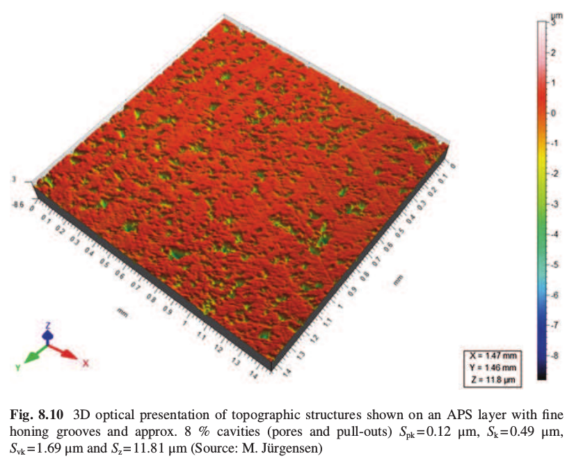
For equally honed cast iron surfaces, the differences between R - and S -values [ 11 ] are of minor importance. However, for a fi nish-honed porous surface of coated bores, the R- and S -values can be completely different, depending by the size and distribution of pores.
Figure 8.10 shows the topographic view of a fi nish-honed APS layer (atmospheric plasma spraying, Sulzer). The advantage compared with the cast iron surface consists in the porous structure. The surface of a thermal-sprayed coating contains cavities of only 8 % of the considered surface. In conventional plateauhoned cast iron, the comparable oil retention grooves however have three times higher part of the surface. However, the oil retention volume of both surfaces is in the same range, which means, thermal coatings have a comparable lubrication conditions but a more completed solid contact to the piston rings. Due to this the conditions of mixed friction are improved with profi le characteristics of fi nish-honed thermal coatings. Additionally the pores as closed micropressure chambers will support the hydrodynamical friction which guides to less friction in lower range of rotational speed range [ 12 ].
With this topographical condition, at the beginning of fi red engine running, a bearing surface is available. The pores are layered immanent features of the honed surface structure. Also after advanced running duration with increasing wear ofmcylinder surface, new pores will always be opened, so that surface relief and its oil retention volume will not change essentially.
6 Summary
Machining of thermal-sprayed layers is a new challenge for new manufacture technologies, in particular for machining cylinder bores with different honing variants. New strategies for machine and tool layouts as well as in particular the availability of appropriate diamond stones considering the material-specifi c properties of the cutting process are essential.
Based on the coating material characteristics which are relevant for machining, a new honing process is presented. There are the material and mechanical properties and the layer structure. Following the general quality values and their functional tolerance ranges are described. Then the different variants of machining strategies are indicated, which are applicable for the different thermal-sprayed layers. The paper is closed by the discussion of the machining results regarding the functional properties, including by the evaluation of 3D surface measuring methods.
The answer to the public discussion of CO 2 reduction of combustion engines with minimized fuel consumption is refl ected by numerous applications of thermalsprayed layers with low friction used for cylinder bores. Honing of thermal-sprayed layers allows specifi c functional tribological surfaces with minimized friction. In general, this contribution to machining processes supports the sustainability of the combustion engine.
References
1. B. Gand: Beschichtung von Zylinderlauffl ächen in Aluminiumkurbelgehäusen, MTZ Motortechnische Zeitschrift 0212011 72. Jahrgang
2. T. Große, A. Gerdes: Honen thermischer Spritzschichten, Portal, Institut für Werkzeugmaschinen und Fertigungstechnik IWF, Technische Universität Braunschweig, Ausgabe 25/Oktober 2012
3. U. Schlegel, S. Flor: Plasmabeschichtung von Aluminium-Zylinderlauffl ächen für Verbrennungsmotoren in der Serienfertigung, 2. VDI Tagung, Zylinderlaufbahn, Hochleistungskolben, Pleuel–Innovative Systeme im Vergleich, 16. und 17.9.2003, München
4. H.-W. Hoffmeister, G. Flores, Ch. Schnell: Vorbehandlung und Honen thermischer Spritzschichten, Jahrbuch Schleifen, Honen, Läppen und Polieren, 63. Ausgabe 11.2007 Vulkanverlag, Essen
5. G. Barbezat, J. Schmid: Plasmabeschichtungen von Zylinderkurbelgehäusen und ihre Bearbeitung durch Honen, MTZ Motortechnische Zeitschrift 62 (2001) 4:2–8
6. G. Flores: Innovative Honverfahren, VDI-Z 152 (2010), Nr. 11/12-November/Dezember
7. Deutsches Patent DE 103 48 419 B3, Verfahren zum Schrupphonen der Mantelfl äche einer Bohrung, Veröffentlichungstag der Patenterteilung 13.01.2005