Form honing new optimisation potential for piston engines
The existing machining of internal combustion engines demands cylinder bores with high cylindricity and surface quality. However, the machining macro shape is not preserved. In operational condition, complex distortive mechanisms occur which deform the cylinder bore. Gehring Technologies has developed a honing process which does not aim at a cylindrical machined shape but which already takes machining deformation into account in order to ensure cylindrical bore surfaces under certain operational conditions.
Authors
- Dipl.-Ing. (FH) Gerhard Flores is Head of Process Development and Patents at Gehring Technologies GmbH, Ostfildern (Germany).
- Dipl.-Ing. Andreas Wiens is Employee in the Powertrain, E-drive (GR/PMP) Department at the R&D Centre Ulm of Daimler AG (Germany).
- Dr.-Ing. Michael Lahres is Team Leader Functional Surface and Machining Processes at the R&D Centre Ulm of Daimler AG (Germany).
- Dr.-Ing. Hans-Werner Hoffmeister is a Director of the Institute of Machine Tool and Production Technology at the Technical University of Braunschweig, (Germany).
Motivation
At present, the most important factor in the development of internal combustion engines for motor vehicles is the reduction of fuel consumption and emissions. The focus is currently on the CO 2 value [g/km]. In order to meet these limits, the aim is to reduce friction inside the engine. Special potential is offered by the optimisation of the tribological system, consisting of the cylinder bore surface and piston rings.
The existing honing process generates cylinder bore surfaces with the smallest possible deviations of a few μm from the ideal cylindrical shape. However, the fired engine does have these high accuracies available, as various kinds of deformations influence the cylinder bore and therefore have an impact on the engine functions. Apart from the machining deviations, there can be deformations of the cylinder bore caused by assembly forces of the cylinder head and other components. Furthermore, there are additional thermal and dynamic deformations which can add up to approximately 40 to 70 μm of local form deviation, depending on the engine design. Due to the limited form filling capacity of the piston rings, only an incomplete geometrical approach to the cylinder bore deviation is possible. Thus, unfavourable influences caused by blow-by and oil consumption can affect the function of the engine.
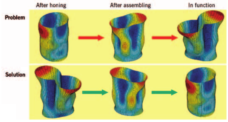
1 Approach of cylindrical distortion compensation
In order to fulfil the related demand for functionally cylindrical bores, a machining process of distortion compensation has been developed. This means that distortion caused by the machining process, which deforms to a more or less cylindrical bore, is preserved after the assembly at a certain operational temperature of the fired engine. Img 1 shows the approach of cylindrical distortion compensation.
Principle of Form Honing
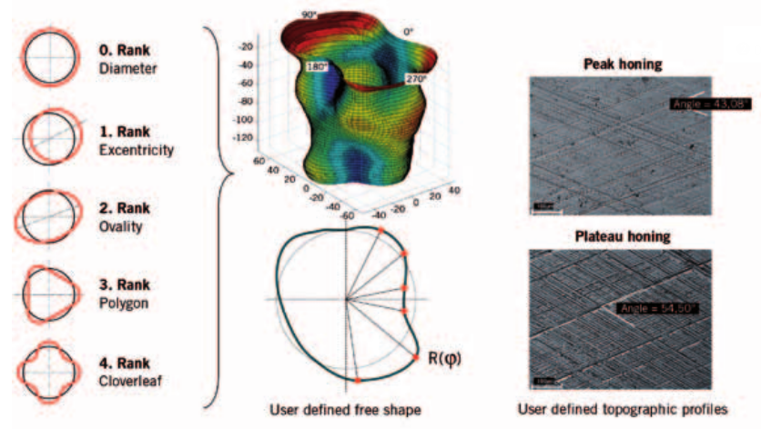
2 Objectives of form honing
In order to define the desired contour (nominal form) to be honed in order to compensate for the function-related cylindrical distortions, an experimental method is applied which is based on a fired engine block with a torque plate for honing [1]. Even if the temperature distribution does not correspond with the condition of a fired engine, the shape shows a smaller cylindrical distortion under functional conditions, after dismantling of the torque plate and cooling down of the engine block, than after the conventional machining process. A further method is the simulation calculation, which can consider the cold static, thermal and dynamic influences. The deformation form obtained is inverted by the form honing process, so that the desired form can be generated by a contour with appropriate stock. The nominal form is defined by R/φ coordinates [2], which describe the free geometry to be honed sufficiently accurately by eight horizontal cutting levels with 256 points each. The goal of form honing, Img 2 , is to generate this form by honing, with the result that any free geometry can be achieved up to harmonic form parts of the eighth order. In addition to this highly resolved functionalnominal form, there is also a demand for standardised roughness profile in all sections of the form honed bore [3]. All kinds of profiles are can be produced within the tolerances for all form-critical features, such as hollows, rises and passages of the free geometry. This applies both to conventional peak honing and to the complex profile definitions of plateau honing.
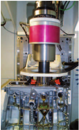
3 Form honing of R4 cylinder block
Process components
Implementing the form honing process, Img 3 , requires a large number of innovations in order to control the working faces of the diamond stones.
The tool concept developed consists of four independently working honing stones. The timing of the radial expansion, expansion force and expansion distance can be controlled with reference to the desired form. The working faces of the tooling follow the desired nominal form by their kinematics and can cut any free geometry into the cylindrical bore. As the four honing stones can only have a limited length due to the shortwaved axial form characteristics, constant contact of the tool working face at any bore position has be assured independently of the local form structure during the complete honing process. This is a function of the process parameters and is dependent on the honing time, honing stone length, stroke speed, stroke acceleration, speed, the number of honing stones and the bore size. In order to meet the existing honing times of cylinder bores of passenger cars < 30 s, cutting speeds that ensure the self-sharpening effect of the metalbonded diamond stones are also needed. At a speed of 400 rpm, for example, with expansion frequencies of up to 32 Hz, form parts of the fifth order with a radial stock of 60 μm can be honed. Higher orders are also possible, as the amplitudes are then generally at a lower level. These independent expansion characteristics of the single cutting stones with regard to dynamics, force and distance are only possible by the use of efficient piezo-electrical regulators.
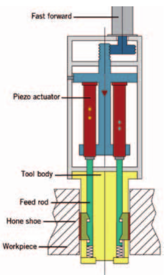
4 Piezo-electrical expansion system
Img 4 shows the piezo-electrical expansion system with rapid expansion, piezo regulators and form honing tool. The rapid expansion activates the complete piezo expansion system, the expansion bars and the honing stones until contact of the working faces with the bore surface is achieved. Starting from this position, the piezo regulators are active and are expanded and locally differentiated according to the desired form. For the control of the honing stones regarding the desired form, the radial nominal values are stored in an expansion matrix, Img 5 . For each form coordinate, there exists a defined voltage with which the piezo regulator is expanded at the desired local position. The voltage values are related with R/φ coordinates to the nominal form. However, they also consider the local transfer characteristics of the tool/ workpiece system. All honing stones of the form honing tool are fed independently of each other according to this expansion matrix and dependent on the
actual bore surface position.
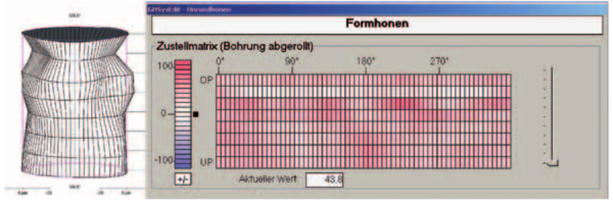
5 Actual form and expansion matrix with nominal form
If, starting with a cylindrical form, the non-cylindrical free geometry is cut into the bore, the final roughness profile has to be prepared by an additional operation. For this purpose, a multi-part tool was developed. The single carriers of the tool have spring-mounted honing stone segments [4]. These segments also have a reduced length to enable them to follow the local form structures. The spring rate of the elastic mounting is so low that there is a constant radial force on the segment shoes for general form structures during contact with the bore surface. This smoothing operation can be performed with one operation for peak honing or with two operations for plateau honing by means of a double-feeding tooling, Img 6 . The smoothing operation can be carried out with diamond stones as well as with ceramic stones.
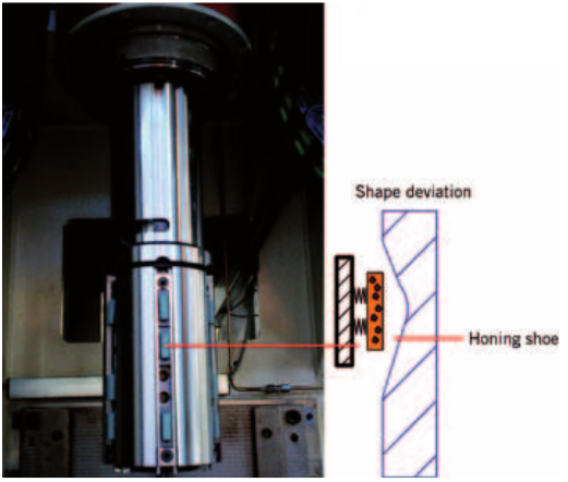
6 Smoothing honing tool with elastic-mounted honing segments
The complete process sequence comprises the cylindrical roughing – depending on the degree of form characteristics – one or two form honing operations and a final smoothing operation. To control the machining process, post-gauging form measuring is necessary. To do this, a pneumatically activated measuring mandrel (Stotz principle) with a measuring range of 150 μm, which measures the bore in 15 s and with a repeatability of ≤ 2 μm, is used. This measuring procedure is insensitive to vibrations and dirt. It can be used in the working area next to the honing spindle. In this way, the bore shape and the diametric value, which is defined as the piston assembly size of the bore, can be determined. The diametric value and the desired form can be stabilised within the tolerances by feedback controls.
Results
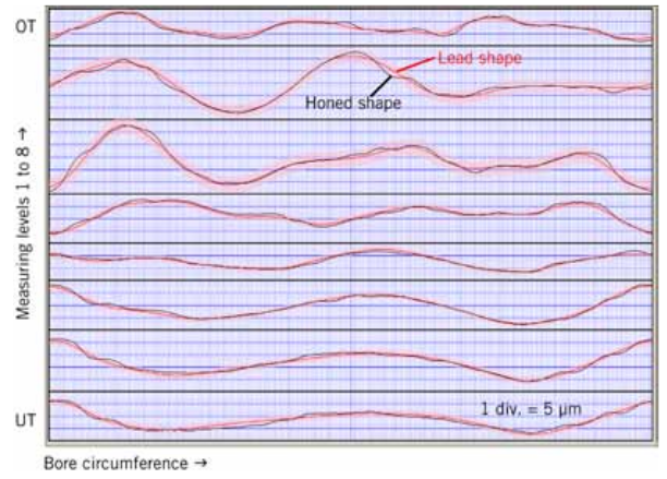
The new form honing process delivers reproducible free geometries within small limits which deviate by a maximum of ± 3 μm from the desired form, Img 7 . This does not include are statistical tolerance limits. The complete stock removal of form honing based on the cylindrical rough honed bore is at least 0.02 mm in diameter, plus a radial form depth depending on the form characteristics. Toleration of the form is performed by the arrangement of envelope curves at the desired tolerance distance the nominal stock. In addition, the amplitudes of the respective order are also to be tolerated. By subtracting the actual form from the nominal form, the influences of higher orders as prejudicial factors to the function can be evaluated. The form honing machining times are approximately 50 s for commercial vehicles and about < 30 s for passenger cars. The piezo-electrical expansion has proven to be a reliable and accurate technology.
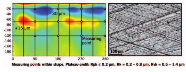
8 Free geometry with plateau profile
In addition to the form, topographies with plateau structures on the complete form honed surface can also be reliably realised. ❽ shows such a plateau profile with measuring points on form rises (+15 μm) as well as on form hollows (-30 μm). The desired tolerances of the surface characteristic values R pk , R k and R vk could be achieved in their entirety. Thus, the surface quality is comparable with conventional serial honing processes.
Outlook
With the developed level of the form honing process, free geometries with more than 50 μm of local form deviation can also be generated. The surface quality and the cycle times correspond to the values of the conventional honing process. Functional advantages of the fired engine could be proved by oil consumption and emissions. As it is a modification of the complete tribological system, the piston ring package of the free geometric surfaces are also to be adapted to the cylinder bore surfaces with regard to pressure force and geometrical shape. Form honing machining enables the substitution of the torque plate and offers not only functional advantages but also machining advantages by cost reduction. The present tool life of the form honing stones is appropriate for small batches. However, there is potential for optimisation. Form honing is an innovative honing process that offers increased efficiency and emission reduction for internal combustion engines. The results are preconditions for the series production of the cylinder blocks examined.
References
[1] Wiens, A.; Lahres, M.; Hoffmeister, H.-W.; Flores, G.: Fertigungstechnischer Ansatz zur K ompensation von Zylinderverzügen mittels Formhonen. VDI-Berichte Nr. 2109, 2010, S. 133-145, VDI-Wissenforum GmbH, Düsseldorf
[2] Flores, G.; Klink, U.; Abeln, T.: Honen von Funktionsformen in Zylinderkurbelgehäusen. VDI-Berichte Nr. 1994, 2008, S. 79-89, VDI-Wissenforum GmbH, Düsseldorf
[3] Wiens, A.; Flores, G.; Klink, U.; Abeln, T.: Makroform- und Mikroformbearbeitung von Z ylinderbohrungen mittels Freiformhonen. Jahrbuch Schleifen, Honen, Läppen und Polieren, Verfahren und Maschinen, 63. Ausgabe, 2007, S. 329-339, Vulkan- Verlag GmbH, Essen
[4] Wiens, A.; Lahres, M.; Hoffmeister, H.-W.; Flores, G.: Formhonen von Zylinderlaufbahnen in Kurbelgehäusen mittels eines piezoelektrischen Formhonwerkzeuges. Jahrbuch Schleifen, Honen, Läppen und Polieren, Verfahren und Maschinen, 64. Ausgabe, 2009, S. 265-280, Vulkan-Verlag GmbH, Essen